(I) Design Drawing
A complete design drawing should be available before construction, including the following information:
1. Circuit number, with power supply points indicated by rectangles.
2. Model and length of heating cable required for the circuit (unit: meters).
3. Length of heating cable required per meter of pipe length (unit: meters), i.e., the winding factor.
4. Length of heating cable required for each valve (unit: meters).
5. List of supporting materials and accessories for the heat tracing system.
6. List of temperature control system components.
7. List of materials required for construction.
8. Design parameters and specifications of the insulation materials used.
(II) Pre-construction Preparation
(A) Piping System
1. The piping system and equipment have been installed.
2. Anti-rust and anti-corrosion coatings are completely dry.
3. The piping system installation complies with the design drawing.
4. All burrs and sharp edges have been filed down.
(B) Heating Cable and Accessories
1. Check for any damage to the heating cable surface.
2. The insulation performance of the heating cable is good (insulation resistance ≥20MΩ when tested with a megohmmeter at 1000VDC).
3. The models of the heating cable and all accessories match the design requirements. (C) Site Preparation
1. Place a roll of heating cable and its spool on a stand near one end of the circuit.
2. Route the heating cable along the pipe, avoiding:
* Placing the heating cable on burrs or sharp edges.
* Pulling the heating cable forcefully.
* Stepping on or placing heavy objects on the heating cable.
(III) Single Heating Cable Installation Method
1. Use fiberglass pressure-sensitive tape or aluminum tape to secure the heating cable to the pipe at intervals of approximately 50 cm.
2. When laying flat, attach the heating cable to the lower 45-degree side of the pipe as much as possible.
3. Reserve 1 meter of heating cable at the power supply point and the end of the circuit.
4. Route the cable according to the [winding factor] shown in the design drawing (if the factor is an integer, lay flat to reduce connection points).
5. For all heat sinks (such as supports, valves, flanges, etc.), reserve the required length of heating cable as per the design drawing, wrap it around the heat sink body, and secure it. Note the following:
* The heat sink should have the required length of heating cable.
* Heating cables can overlap or cross each other.
* The winding method should allow the heat sink to be removed for maintenance or replacement without damaging the heating cable or affecting other circuits.
* At two-way or three-way fittings, reserve 40 cm of heating cable at each end.
(IV) Spiral Winding
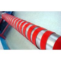
If the winding factor is 1.4, meaning 5 meters of pipe requires 7 meters of heating cable, first secure both ends of the 7-meter heating cable to a 5-meter pipe section, then wind the slack cable around the pipe and secure it.
(V) Multiple Heating Cable Installation Method
1. When the design drawing specifies a winding factor (n=1,2…), generally used for large-diameter pipes, the methods are as follows:
* Route the heating cable from one end of the pipe circuit to the other end and back to the starting point, with the number of passes equal to the factor. (Note the maximum usable length.)
* Route the heating cable from one end to the other end sequentially, with the number of passes equal to the factor.
* Backup system: critical pipes are used for emergency backup. Therefore, each circuit should be installed as an independent circuit with its own power supply point.
(VI) Accessory Installation
* Select accessories according to the design drawing.
* The sealing gasket used must match the heating cable and be combined with waterproof sealant.
* Place the power supply junction box as close as possible to the power supply end of the pipe circuit.
* Prepare the wire ends according to the accessory installation instructions.
* Reserve a short section of heating cable at each wire end for future maintenance.
(VII) Inspection and Testing Before Insulation Installation
* Inspect the heating cable surface for damage.
* Check that all accessories are fully installed.
* Use a megohmmeter at 2500VDC to test each independent circuit at one end; the insulation resistance should be above 20MΩ. Note that the test should last at least one minute, i.e., test between the conductor and the metal braid of the heating cable.
* Record the test results on the installation record sheet.
(VIII) Insulation Layer Installation
Install the insulation layer immediately after testing the heating cable, and note the following:
* The material, thickness, and specifications of the insulation layer must comply with the design drawing.
* The insulation material must be dry during installation.
* A waterproof outer cover should be added over the insulation layer.
* Avoid damaging the heating cable during insulation installation.
* Perform an insulation test on the heating cable immediately after installing the insulation layer.
* Attach a warning label on the insulation layer indicating "Heating Cable Inside" and also mark the locations of all accessories.
(IX) Low-Temperature Start-up and Safety Protection:
Electric heat tracing projects are generally started in groups under normal conditions according to the design drawing, with conventional control design, including switch start, overload protection, and leakage protection. If used for low-temperature high-power heating and started at low temperature, the instantaneous starting current converts to high-power output. A double-throw switching device can be used, and the working current should be monitored during switching, transitioning to the overload protection system under safe load conditions.
(X) Explosion Protection:
* Our company's explosion-proof heating cables can be used in Zone 1 and Zone 2 explosion-proof areas of factories. During installation, avoid areas where flammable gases or liquids may accumulate, such as dark corners, which may exceed the specified explosion-proof zones. Non-explosion-proof distribution boxes should be installed in non-explosion-proof areas; otherwise, corresponding explosion-proof distribution boxes should be configured.
* In addition to the explosion-proof class, pay attention to the explosion-proof group.
(XI) Special Precautions
* It is strictly prohibited to mix steam tracing and electric heat tracing in the same system.
* When installing the heating cable, do not damage the insulation layer. It should be tightly attached to the heated object to improve thermal efficiency. If the object to be traced is non-metallic, use aluminum adhesive tape to increase contact heat transfer area and secure with nylon ties. It is strictly forbidden to use metal wire for binding.
* At flanges, where media are prone to leakage, avoid winding the heating cable directly underneath.
* One end of the heating cable is connected to the power supply; the other end's conductors must not be short-circuited or come into contact with conductive materials. Cut the end into a "V" shape and use the matching end cap to seal tightly.
* In fire and explosion-proof areas, use explosion-proof junction boxes and end terminations.
After wiring, seal with silicone rubber: (For heating cables with a braid, strip 10 cm of the braid at the end to prevent short circuits.)
* Measure insulation once per heat tracing point. The braid must be grounded, and the insulation resistance must not be less than 20 megohms/1000V.
* Set the on/off and leakage protection devices according to the voltage, current, and other parameters of each heat tracing circuit.
* Steam purging: For pipes requiring steam purging to remove scale, first purge and then install the heating cable. If annual purging inspection is required, design and install according to special conditions.
(XII) Acceptance:
This manual does not include the relevant provisions of the installation engineering construction and acceptance regulations or the "Explosion-proof and Fire-proof Regulations." Construction should still comply with the above technical common specifications, which are not repeated here.