
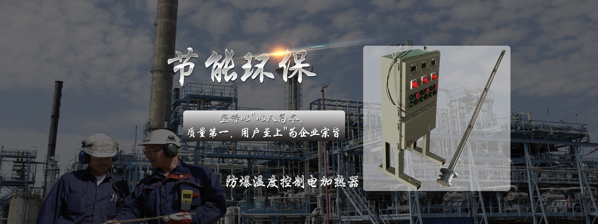
When the hydraulic station of a hydraulic system operates in an ambient temperature below 15°C (or a certain temperature value required by some hydraulic systems) during low-temperature startup, an electric heater needs to be configured to raise the working medium to an appropriate value, reducing the viscosity of the working medium to facilitate oil suction and startup of the hydraulic pump. During the design of the hydraulic station, the designer must select the model of the electric heater according to actual usage requirements. Some key parameters need to be controlled during selection to avoid damage to the working medium and safety hazards. The following is a brief analysis of the design, selection, and use of common electric heaters.
1 Selection of Immersion Tube Electric Heaters
1.1 Basis for Selection of Immersion Tube Electric Heaters
1) Surface Load
Surface load, i.e., the power per unit area on the heating surface, also known as area heat dissipation power or surface power density, mainly relates to the thermal stability of the heated hydraulic working fluid. Excessive surface load can cause aging of the hydraulic working medium and safety issues. When selecting, the main considerations are whether the heater is installed in a non-flowing or flowing medium (e.g., some hydraulic stations have their own circulation system, and the heater is installed in the circulation pipeline) and the type of hydraulic working medium. Reference can be made to relevant standards and recommended regulations as shown in the following table; or contact the manufacturer of the working medium to determine the appropriate surface load range.
Table 1 Surface Load
Surface Load W/cm2 | Heating Medium, Heating Characteristics and Code | Metal Tube Material and Grade |
5 | Boiling of water, weak acid, weak alkali solutions, S | Aluminum L1-L4 |
7 | Copper T4 | |
9 | Carbon Steel 10 | |
11 | Stainless Steel 0Cr18Ni11(1Cr18Ni9Ti) | |
→0.7 | Cooking Oil, Lubricating Oil, Hydraulic Oil, Y | Copper T4, Carbon Steel 10, Stainless Steel 0Cr18Ni11 (1Cr18Ni9Ti) |
Table 2 Hydraulic Medium and Corresponding Static and Flowing Hydraulic Medium
Hydraulic Medium Type | Surface Load (W/cm2) | |
Static Hydraulic Medium | Flowing Hydraulic Medium (≤2m/s) | |
Mineral Hydraulic Oil HLP | 0.7 | 2 |
Oil-in-Water Emulsion HFA | 0.7 | |
Water-Glycol Fluid HFC | ||
Phosphate Ester Fluid HFD-R | 2 | |
Organic Ester Fluid HFD-U | 0.7 | |
Glycerol Ester Fluid HETG | ||
Synthetic Ester Fluid HEES | ||
Polyglycol Fluid HEPG | ||
2) Maximum Temperature
Refers to the maximum temperature of the heater sheath. For general L-HL/L-HM anti-oxidation and anti-rust hydraulic oil, it should generally not exceed 120°C, also for thermal stability and safety of the working medium. It should be noted that the flash points of different hydraulic oils vary, as shown in Table 3. In this case, the maximum temperature of the heater for that type of oil should be 20°C lower than the specified flash point, or consult the oil supplier for a reasonable recommended value.
3) Temperature Measuring Element
Generally, an element independent of the heater should be selected to avoid failure to reflect the true oil temperature in a timely manner when a combined integrated type fails.
1.2 Calculation Content for Immersion Tube Electric Heaters
The calculation content mainly determines the total power of the electric heater, based on the minimum design temperature and heating time specified in the design task.
1) Heating Time
Heating time is the time required to heat the hydraulic oil from the minimum design temperature specified in the design task to 15°C (or a certain temperature value required by some hydraulic systems for constant temperature operation before work starts), i.e., the preparation time required for the hydraulic system to work. It can be determined according to the design task. When the main equipment has a main drive transmission gearbox, it can be consistent with the heating time of the gear oil in the gearbox. Some follow design habits such as 15 minutes.
2) Total Power Required for the Heater
After determining the heating time and oil type, the total power required for the heater can be calculated. It is the sum of the power Pw required to heat from the design temperature (low value T1) to the predetermined temperature (T2) and the power Qw required to maintain heat balance between the ambient temperature (T1) and the predetermined tank temperature (T2), i.e., P = Pw + Qw:
Pw = VB c ρ (T1 - T2)
Z
Where Pw — Power required for heating, kW;
T1 — Design temperature of hydraulic oil, low value in °C;
VB — Volume of hydraulic oil to be heated, dm3;
T2 — 15 or a certain temperature value, °C;
c — Specific heat of hydraulic oil, kWh/kgK;
Z — Heating time, h;
ρ — Density of hydraulic oil, kg/dm3;
Table 4 Hydraulic Medium Types and Corresponding Specific Heat and Density
Hydraulic Medium Type | Specific Heat c (kWh/kgK) | Density ρ (kg/dm3) |
Mineral Hydraulic Oil HLP | 0.000 52 | 0.88 |
Oil-in-Water Emulsion HFA | 0.001 16 | 0.99 |
Water-Glycol Fluid HFC | 0.000 92 | 1.08 |
Phosphate Ester Fluid HFD-R | 0.000 35 | 1.25 |
Organic Ester Fluid HFD-U | 0.000 57 | 0.92 |

After determining the total power of the heater, if the tank installation space permits, it is advisable to select heaters with smaller power and more units.