Dare Electric Heating News; Currently, most continuous reforming units under construction or in operation in China adopt the process package or patented technology of UOP (Universal Oil Products Company). The core of continuous reforming technology is the online regeneration and recycling of spent catalysts without shutdown. Coked catalysts are lifted from the reactor bottom through the spent catalyst valve group using nitrogen to the separation hopper for sorting. After sorting, the catalyst pellets enter the regenerator for coke burning, oxychlorination, drying, and cooling. After regeneration, they are lifted to the reduction section of the reforming reactor for reduction and then re-enter the reaction. Among these, controlling the inlet temperature of the regenerator drying zone is particularly important because the moisture content of the catalyst has strict requirements, directly affecting the catalyst life. The inlet temperature of the drying zone is achieved by the air electric heater.
1. Process Flow and Piping Layout
Figure 1 shows the flow diagram from the air electric heater to the regenerator drying zone inlet. According to UOP requirements, the geometric length of this pipeline must not exceed 3m, and the thermocouple TE3045 must be within 0.6m from the regenerator. Based on these requirements, there are usually two layout methods as shown in Figure 2 and Figure 3. Figure 2 shows the electric heater close to the regenerator, with a pipeline geometric length of 3.6m. As shown in Figure 3, the electric heater outlet is directly opposite and at the same elevation as the drying zone inlet, with a pipeline geometric length of 1.0m. In both layouts, the air electric heater is within the framework.
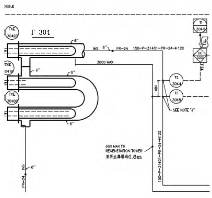
Figure 1 Flow diagram from air electric heater to regenerator drying zone inlet
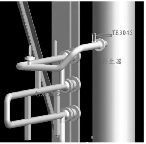
Figure 2 Layout with electric heater close to regenerator
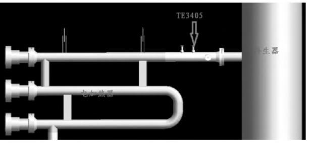
Figure 3 Layout with electric heater outlet directly opposite drying zone inlet
Temperature Drop
2. Scheme Comparison
2.1 Pipeline Temperature Drop
Under normal conditions, this inlet pipeline requires insulation to reduce temperature drop, thereby achieving the 565°C required by UOP. However, in a newly started refinery, the inlet temperature could not reach this value, with a maximum of only 490°C. After analysis and investigation, it was found that the pipeline insulation was substandard. The pipeline in this refinery was arranged according to Figure 2. Without considering other factors, assuming laminar flow inside the pipe, according to Newton's cooling formula: Q = KAΔtm, under the same conditions, the larger the heat transfer area, the greater the heat loss. It is easy to see that if the on-site insulation is substandard, the layout in Figure 2 will have greater heat loss than that in Figure 3, making it difficult to meet the inlet temperature requirement, thereby increasing the catalyst moisture content, affecting catalyst performance, and ultimately affecting the quality of reforming products.
2.2 Pipeline Thermal Stress
Screenshots of thermal stress calculation software for the relevant pipelines under the two layouts are shown in Figures 4 and 5.
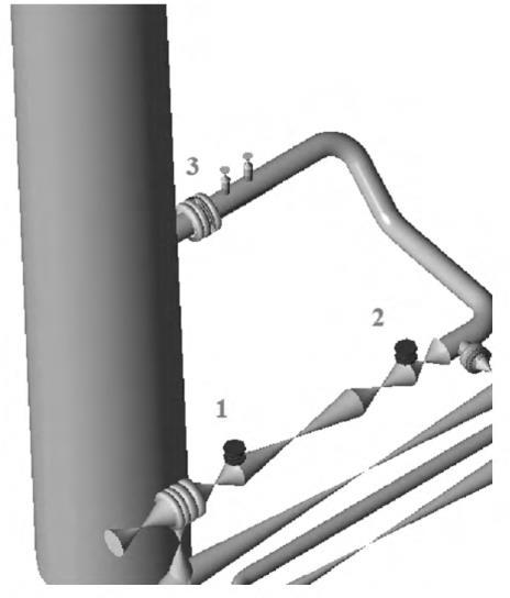
Figure 4 Screenshot of thermal stress calculation software for layout with electric heater close to regenerator
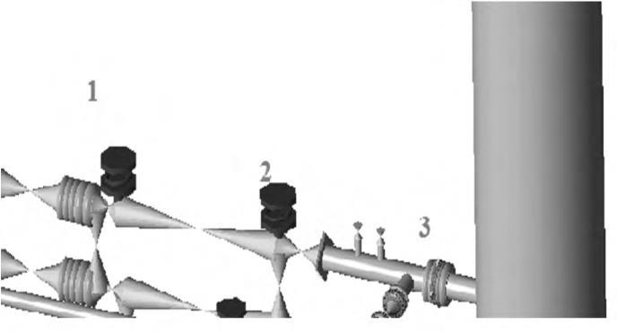
Figure 5 Screenshot of calculation software for layout with electric heater outlet directly opposite drying zone inlet
Both layouts require spring hangers at points 1 and 2. However, because Figure 4 has a horizontal pipe section that can absorb thermal expansion, there is no horizontal displacement. In Figure 5, since it is directly connected to the equipment nozzle, horizontal displacement may occur, so guide supports are needed at points 1 and 2. Calculations show that in Figure 4, the vertical loads at points 1 and 2 are 9751N, the vertical load at equipment nozzle 3 is 895N, and the horizontal load is 1224N. In Figure 5, the vertical load at point 1 is 11397N, at point 2 is 6448N, the vertical load at equipment nozzle 3 is 2259N, and the horizontal load is 5141N. From the above data, the electric heater layout in Figure 2 is better than that in Figure 3 from the perspective of piping system stress.
2.3 Heat Exchanger Bundle Pulling for Maintenance
The structure of the air electric heater is shown in the figure below. Both the terminals and tube bundles require pulling for maintenance. Due to strength requirements, the structure must be supported at the positions shown. The layout in Figure 2 is affected by the electric heater's bundle pulling length, whether pulled by hand or tools. If the manufacturer makes the tube bundle long, it will seriously affect the pulling maintenance of the electric heater. The layout in Figure 3 is less constrained by the tube bundle length; as long as the bundle is within a reasonable range, sufficient space for pulling can be ensured.
3. Summary
By comparing the two air electric heater layouts, it is easy to see that from the perspective of effectively reducing temperature drop caused by abnormal conditions (substandard pipeline insulation) and maintenance, the layout in Figure 3 is more reasonable. From the perspective of piping thermal stress, the layout in Figure 2 can well meet the thermal stress requirements. However, by adjusting the spring hanger loads and adding guide supports, the layout in Figure 3 can also meet the piping stress requirements. Therefore, considering all factors, it is recommended to adopt the layout in Figure 2.