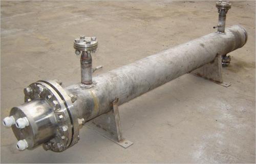
Based on the temperature conditions of a tube sheet in an air electric heater, the tube sheet structure design and tube sheet strength calculation are rationally designed. The design pressure of this air electric heater is MPa 2.0, the design temperature is 440°C, the medium is air, the electric heating power is 1200KW, and the main pressure-bearing components are made of 16Mn and Q345R.
The tube sheet of this air electric heater is equivalent to the tube sheet of a U-tube heat exchanger (without tube box and partition plate). The tube hole diameter on the tube sheet is Φ22.5 mm, and a section of sleeve with specification Φ22×2.5 mm is welded in each tube hole. The U-tube electric heating element has a diameter of Φ16 mm. The electric heating element extends out of the sleeve and enters the wiring compartment at the top of the equipment. A seal weld is used between the electric heating element and the outer end face of the sleeve. The section from the wiring end to the insulation baffle below the tube sheet is the non-heating zone. The tube holes on the tube sheet are arranged in concentric circles. From the outermost circle inward, the number of tube holes on each adjacent two circles of hole arrangement circles is equal. The U-tube electric heating elements span across the tube holes in these adjacent two circles. The innermost circle of 6 tube holes is interspersed with 3 U-tube electric heating elements of different lengths in a plum blossom pattern. A thermocouple sleeve is installed in the center hole.
According to the container design pressure P=2.0MPa and design temperature t=440°C, the container flange material is 16Mn forging. According to NB/T47020~47027-2012 "Pressure Vessel Flanges, Gaskets, Fasteners", the container flange is selected as a long-neck flange with nominal pressure PN4.0, flange outer diameter Φ1215 mm, stud specification M30, quantity 48 pieces, stud material 35CrMoA, and gasket using spiral wound gasket. Based on the above conditions and parameters, the thickness of the tube sheet is calculated using calculation software, and the design thickness is obtained as δ=124 mm (where the sum of opening widths on the dangerous radial section of the flat cover is Σb=420mm).
From the above calculation results, it can be seen that if the tube sheet is calculated according to the design temperature of the container, the design thickness of the tube sheet is relatively large. However, the gas at 150°C enters the container from the upper nozzle and flows downward, is heated by the electric heating elements, the temperature rises, and after heating ends, the temperature rises to 420°C, and flows out from the lower nozzle of the container. During this process, the gas temperature gradually increases. The gas just entering the upper part of the container has not been heated yet. The temperature of the tube sheet and container flange in contact with the gas is only about 150°C, and there are two layers of baffles below the tube sheet for insulation. The temperature of the shell gradually increases from 150°C at the gas inlet end to 420°C at the gas outlet end. Therefore, it is unreasonable to set the design temperature of the tube sheet to be the same as the design temperature of the container shell. According to the structure and operating conditions of this electric heater, we believe that the design temperature of the tube sheet can be reduced, and it is unnecessary to take the design temperature of the container shell. Clause 4 of Article 5.0.1 of HG/T 20580-2011 "Specification for Design Basis of Steel Chemical Containers" stipulates that when the metal temperatures of various parts of the container under working conditions are different, the design temperatures of each part can be set separately. Considering the heat conduction of the shell and the heat transfer of the electric heating elements, the temperature of the tube sheet is higher than the gas temperature, and this temperature difference is estimated to be about 30°C. Therefore, the actual temperature of the tube sheet is approximately 180°C. Considering a certain design margin, it is safe to set the design temperature of the tube sheet to 200°C. The container flange is in the same situation as the tube sheet, and its position is also above the low-temperature gas inlet. The actual temperature will not exceed 200°C, so it should be safe to set the design temperature of the container flange to 200°C. When the design temperature of the container flange is taken as 200°C, the nominal pressure of the flange can be selected as PN2.5, flange outer diameter Φ1195 mm, stud specification M27, quantity 36 pieces, stud material 40MnB. Using the above conditions and parameters, recalculate with SW6 calculation software, and the design thickness of the tube sheet is obtained as δ=88 mm. Through the above analysis and calculation, according to the working conditions of the electric heater, after setting the design temperatures of the shell, tube sheet, and container flange separately, the design thickness of the tube sheet is reduced from 124 mm to 88 mm, significantly thinning the tube sheet thickness and reducing material consumption. Of course, if different pressure-bearing components on a container are set with different design temperatures, the main pressure-bearing components corresponding to different design temperatures should be listed in the design data table on the general arrangement drawing of the equipment.
For pressure vessels such as electric heaters, because the temperature of the medium gradually increases from the inlet to the outlet, the metal temperatures of various parts of the shell are different. Therefore, when performing strength calculations, if the pressure-bearing components in the low-temperature area are calculated according to the design temperature of the container, the required thickness is larger. According to the working conditions, the possible metal temperature of the component can be determined separately, and its design temperature can be set, and then the required thickness of the component can be calculated.
The air electric heater described in this article has the tube sheet equipped with electric heating elements in the low-temperature area, i.e., the low-temperature gas enters the electric heater shell from a position close to the tube sheet. If the temperature difference between the gas inlet and outlet is large, setting the design temperatures of the tube sheet and shell separately can significantly reduce the design thickness of the tube sheet, which can not only reduce material consumption but also shorten the machining time of the tube sheet, especially the drilling time of tube holes.