
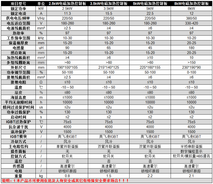
Parameters of 2.5-8kW Electromagnetic Heating Control Board:
Wiring Instructions for Electromagnetic Heating Control Board
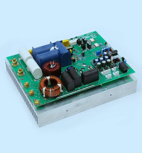
1. Three indicator lights: "Power", "Operation", and "Fault". During normal operation, "Power" and "Operation" are on, and "Fault" is off. When a circuit fault occurs, the "Fault" light flashes.
2. Connect the 220V power supply to the terminal marked "220V Power Input". It does not matter which wire (live or neutral) goes where; just connect them arbitrarily.
3. Connect the coil to the two terminals marked "OUT1" and "OUT2". Tighten the screws securely.
4. This board is factory-set to operate when power is supplied. At this time, the "Switch Control" socket has a shorting jumper (black) that shorts the socket. You can also gently remove the shorting jumper (black) from the "Switch Control" socket, insert one end of a two-core connecting cable into the "Switch Control" socket, and connect the other two plugs to the normally open contacts of a thermostat. Then you can test the machine.
Installation of Electromagnetic Heating Control Board
1. Control box requirements: Since the main controller is a high-voltage, high-current device, it should be installed inside a control box during use, and then connected to the heating coil, power supply, temperature controller, and other devices via insulated wires. This protects the human body from touching live parts and causing electric shock. Since the controller itself generates heat, the control box should be designed to allow air circulation for heat dissipation.
2. Heating coil: Use appropriately specified insulated high-temperature wires for winding. Typically, it is a circular coil. Measure the inductance with a Victory BICTOR6243+ inductance meter. Wind it around the barrel and measure. The number of turns varies depending on the barrel diameter; adjust according to actual use.
3. Winding the heating coil: Wind the heating coil according to the user's specific requirements. Ensure that the winding direction and parameters of the heating coil on the same iron core are consistent. Maintain a distance of at least 50mm between each coil group.
4. Distance between heating coil and heated metal object: Adjust the distance from the coil surface to the heated metal object surface appropriately based on the coil width. Adjust the distance according to the pipe diameter; larger diameter requires closer distance, smaller diameter requires farther distance. Generally, it is 15-22mm. If the distance is too small, the control board may overheat due to degraded performance, or even cause power tube explosion. If the distance is too large, the power will gradually decrease and cannot be adjusted, due to circuit back-voltage protection.
5. Wiring methods: This controller can be configured for power-on startup or controlled by the normally closed contacts of a thermostat.
a. Power-on startup: Connect the 220V power supply to the controller's live and neutral terminals via insulated wires. Connect the coil lead terminals to the controller's coil connection terminals (ensure a firm connection). This board is factory-set for power-on startup mode.
b. Control using normally open contacts of a thermostat: Connect the 220V power supply to the controller's live and neutral terminals via insulated wires. Connect the coil lead terminals to the controller's coil connection terminals (ensure a firm connection). Gently remove the shorting jumper (black) from the "Switch Control" socket, insert one end of a two-core connecting cable into the "Switch Control" socket, and connect the other two plugs to the normally open contacts of the thermostat. Then you can test the machine.
Note: The thermostat contacts must not carry mains voltage or other high voltage. C. Multi-board connection: When a single thermostat contact needs to control multiple boards to start and stop simultaneously, first designate one board as the master board (choose any board). Then use a connecting cable (two-core wire with a 2-pin plug at each end) to connect the "Slave Board Control" on the master board to the "Voltage Control" on another slave board. To connect more slave boards, use connecting cables to connect them level by level: connect the "Slave Board Control" of one slave board to the "Voltage Control" of the next slave board, and so on.